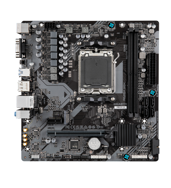
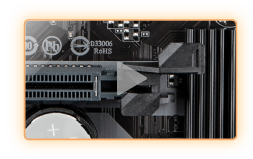
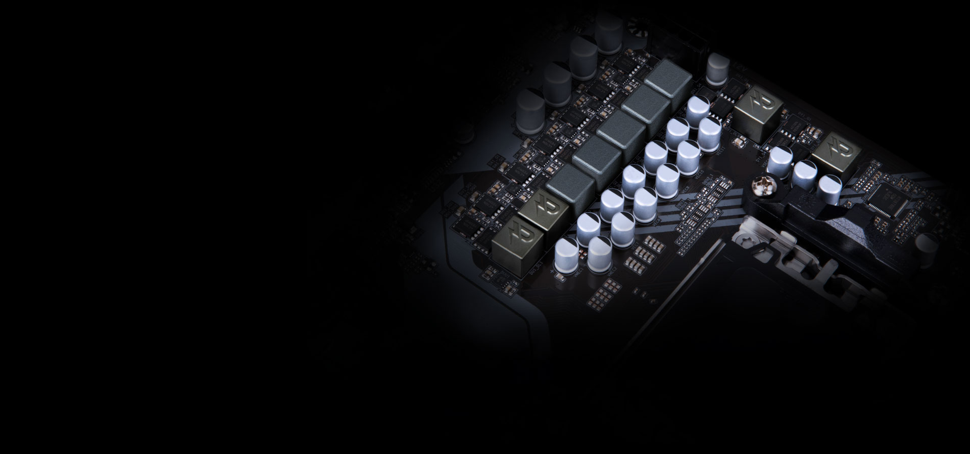
GIGABYTE UD series motherboards use a 5+2+2 phases digital PWM + Low RDS(on) MOSFETs design to support AMD's new generation CPU by offering incredible precision in delivering power to the motherboard's most power-hungry and energy-sensitive components as well as delivering enhanced system performance and ultimate hardware scalability.
Características principales
OVERVIEW
PERFORMANCE
CONNECTIVITY
PERSONALIZATION
ULTRA DURABLE
Performance
Connectivity
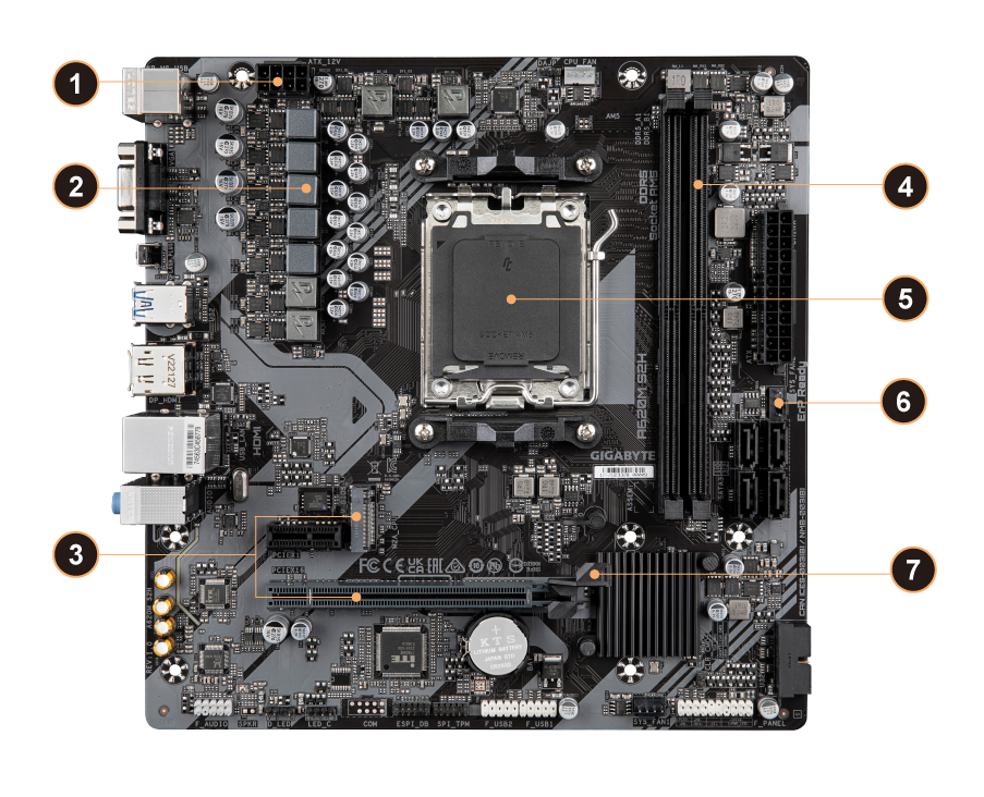
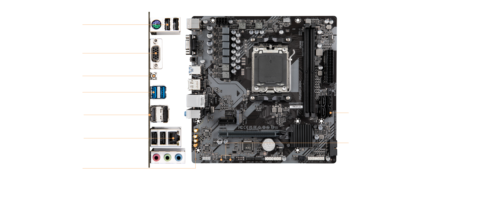
1
Solid Pin CPU Power Connector
2
5+2+2 Digital VRM Design
3
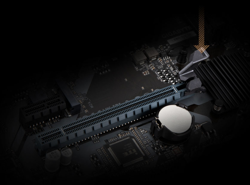
PCIe 4.0 Design
- 1*PCIe 4.0 x16 slot
- 1*PCIe 4.0 x4 M.2 Connector
4
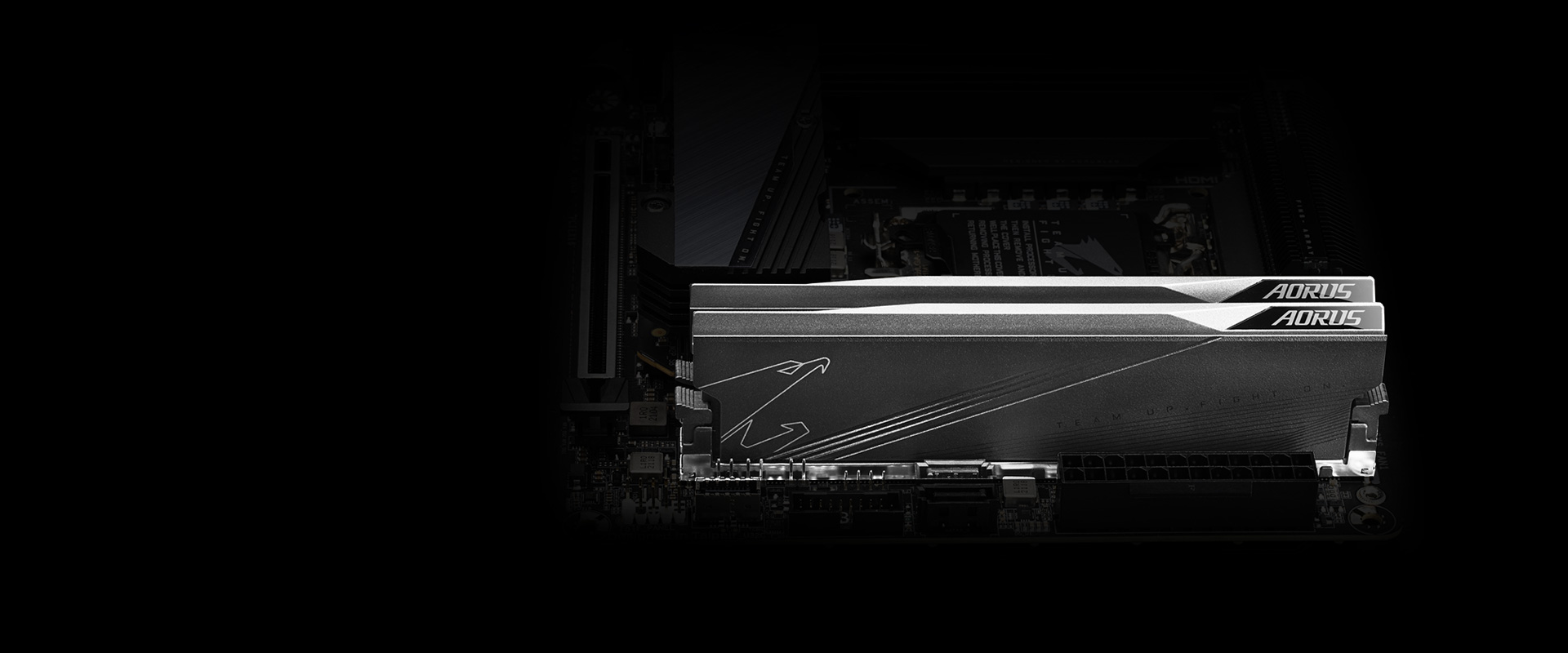
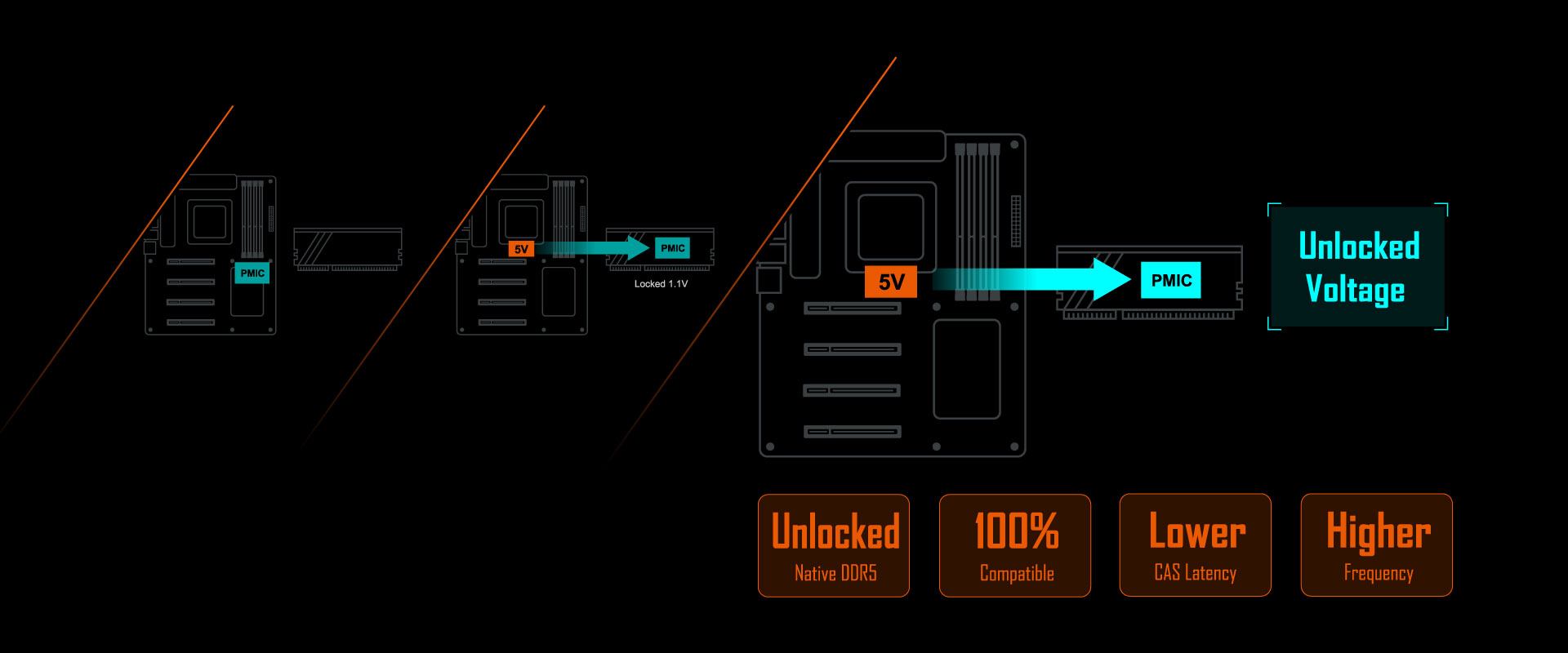
Dual Channel SMD DDR5 Memory
5
Socket AM5 Supports AMD Ryzen™ Series Processors
6
Smart Fan 6
- 3*PWM/DC Fan Headers
- Dual Fan Curve Mode
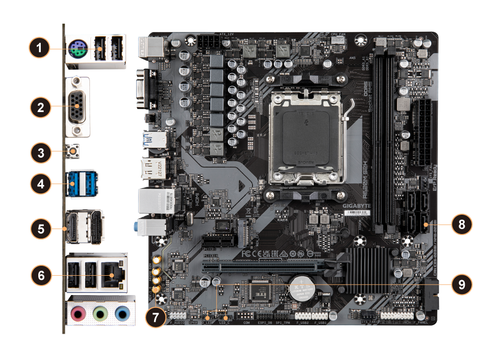
1
4*USB 2.0
2
D-Sub
3
Q-FLASH PLUS Button
4
2*USB 3.2 Gen1
5
HDMI, DisplayPort
6
GbE LAN
7
Hi-Fi Audio
- 8-Ch HD Audio
- Audio Noise Guard
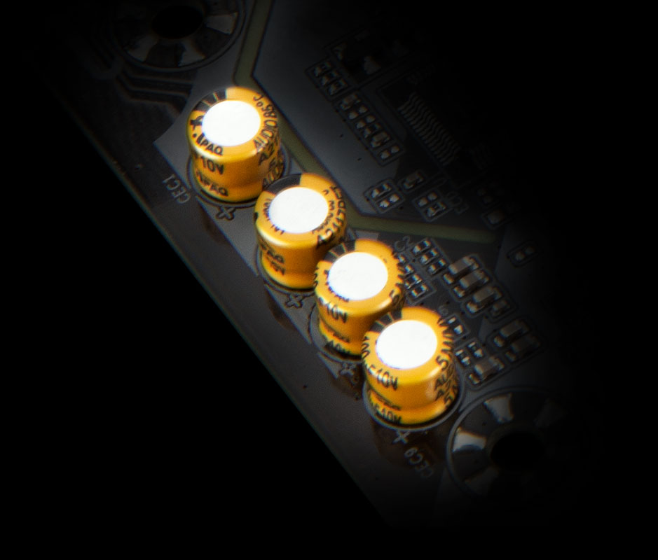
- High-End Audio Capacitor
8
4*SATA 6Gb/s
9
RGB FUSION
- 1*Addressable LED Header
- 1*RGB LED Header

PERFORMANCE
PERFORMANCE
Digital VRM Design
PCIe 4.0 Hardware Design
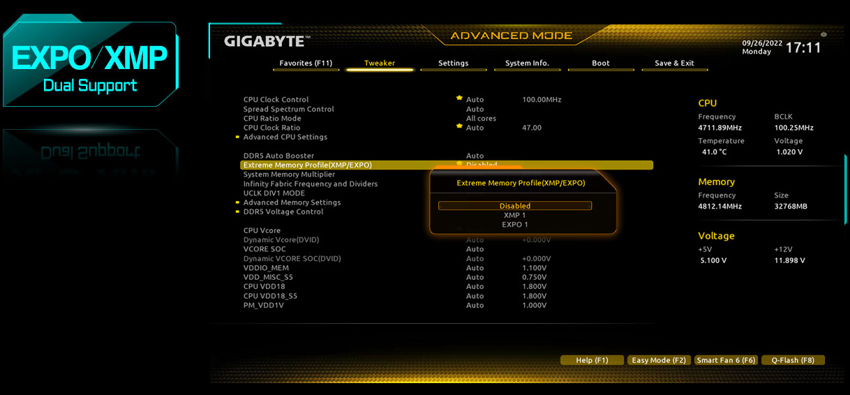
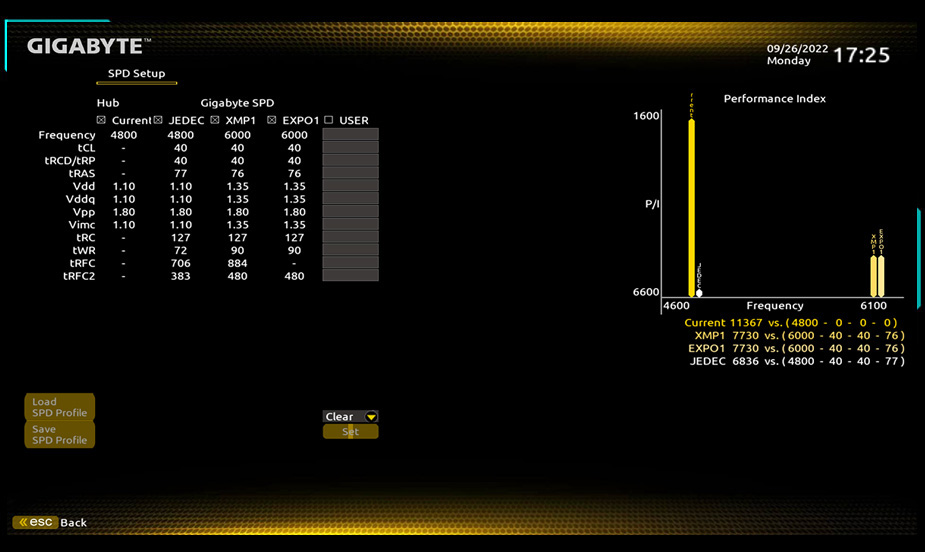
EXPO & XMP Support
Smart Fan 6

5+2+2 Phases Digital VRM Solution with Low RDS(on) MOSFETs
Benefits of Low RDS(on) MOSFETs
‧ Optimized gate charge to minimize switching losses.
‧ Lower temperature, smaller size, better thermal characteristics.
‧ Lower temperature, smaller size, better thermal characteristics.

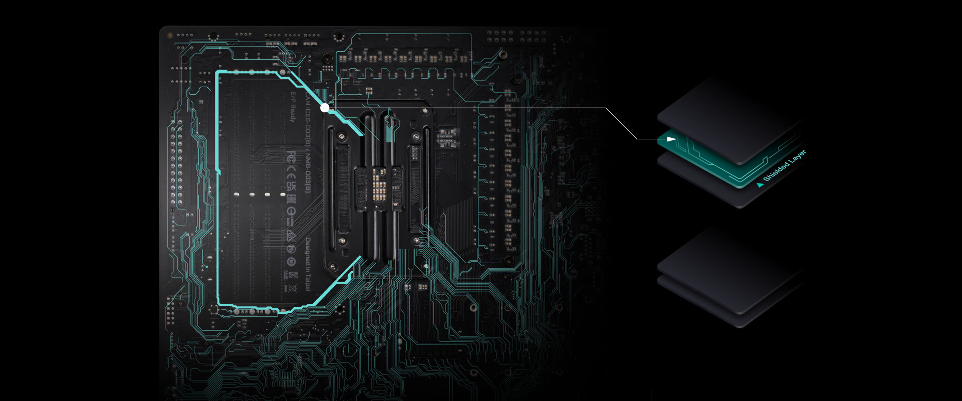
GIGABYTE A620 Motherboards are ready to work with the PCIe 4.0 devices which are expected to experience twice bandwidth than the current PCIe 3.0 devices. To reach the high speed and maintain good signal integrity, GIGABYTE R&D uses the low impedance PCB to provide the maximum performance.
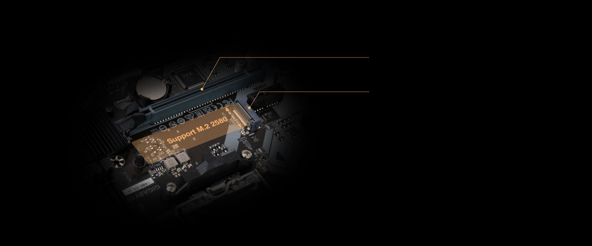
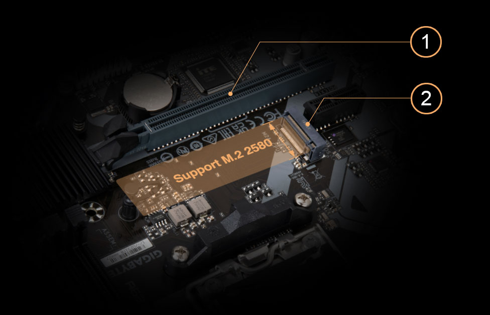
1. PCIe 4.0 x16 slot with faster bandwidth and lower impedance.
2. M.2 PCIe 4.0 x4 slot with lower impedance.


CONNECTIVITY
CONNECTIVITY
GbE LAN
Hi-Fi Audio
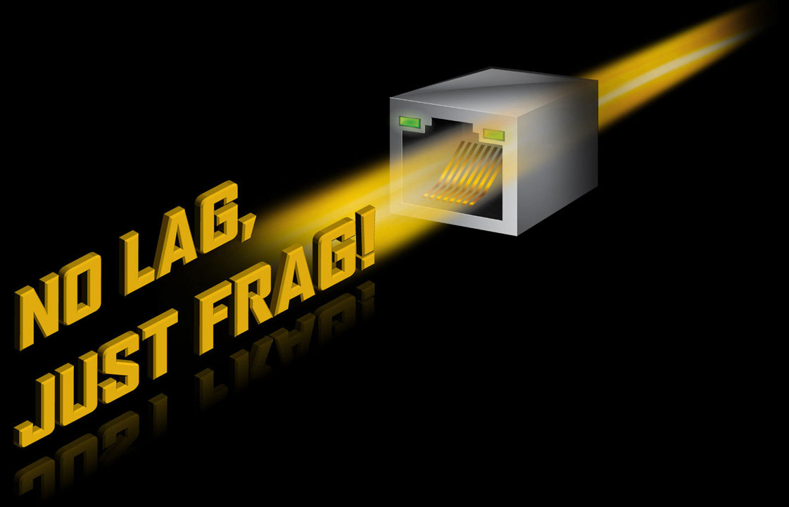
GbE LAN with Bandwidth Management
GbE LAN features a network bandwidth management application which helps to improve network latency and maintain low ping times to deliver better responsiveness in crowded LAN environments.

PERSONALIZATION
PERSONALIZATION
UEFI BIOS
GIGABYTE Control Center
Friendly User Interface
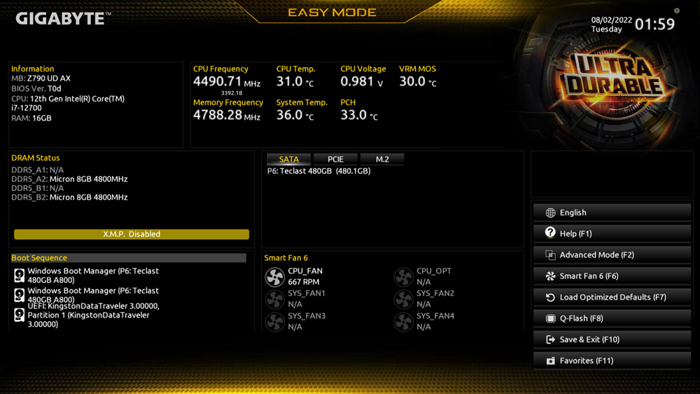
The EASY MODE shows important hardware information in one page including CPU clock, Memory, Storage, Fan.
My Favorites
Add constantly used items into the favorite menu for quick access.
Storage Information
Show all kinds of storage information including SATA, PCIE and M.2
interface.
Changelog
List all changes before saving and exiting bios. Quickly review overall
settings
modification.
Intuitive Load Line Curve
Clearly show each loadline calibration setting in an intuitive curve graph.

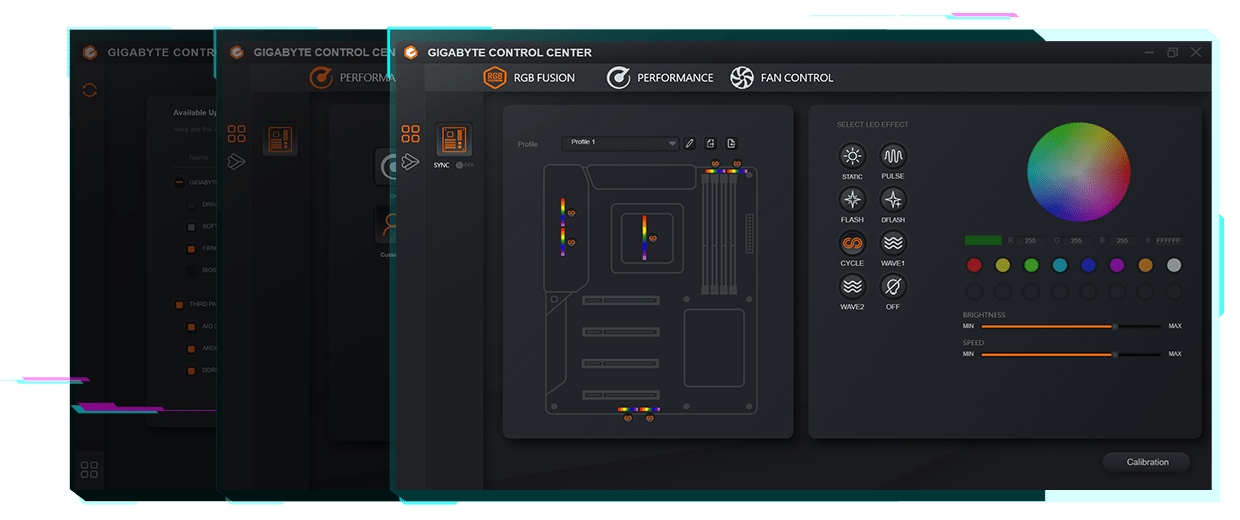
GIGABYTE CONTROL CENTER (GCC) is a unified software for all GIGABYTE supported products. It provides newly designed intuitive user interface to control all essential function.
- Unified software platform for all Gigabyte supported products
- Intuitive user interface for an eased experience
- Modularized control components only for installed hardware
- Auto update function to keep system up to date and support future products

ULTRA DURABLE
ULTRA DURABLE
DIY Friendly
Q-Flash Plus

Q-Flash Plus
Update the BIOS easily without installing the CPU, memory and graphics card.
With GIGABYTE Q-Flash Plus, you don't need to install the CPU, memory and graphics card nor enter the BIOS menu to flash the BIOS. Just download and save a new BIOS file (rename to gigabyte.bin) on the USB flash drive, then press the dedicated Q-Flash Plus button and you’re good to go!
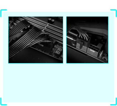
STEP 1.
Plug 24pin & 8pin power supply cable on motherboard

STEP 2.
Download motherboard BIOS file and rename to "gigabyte.bin", save to USB flashdrive, and plug USB flashdrive into Q-Flash USB port
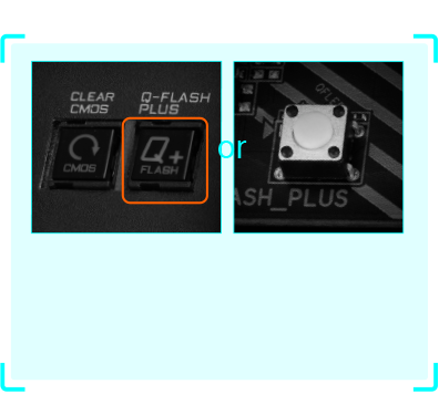
STEP 3.
Press Q-Flash Plus button, and motherboard will start updating BIOS automatically.

* Los términos HDMI, HDMI High-Definition Multimedia Interface (Interfaz multimedia de alta definición), HDMI Trade Dress (diseño e imagen comercial HDMI) y los logotipos HDMI son marcas comerciales o marcas registradas de HDMI Licensing Administrator, Inc.
* Las especificaciones del producto y su apariencia pueden ser diferentes de un país a otro. Te recomendamos que compruebes las especificaciones y apariencia disponibles en tu país con tu vendedor local. Los colores de los productos pueden no ser perfectamente exactos debido a las variaciones causadas por las variables fotográficas y los ajustes de color de tu monitor, por lo que pueden ser diferentes a los colores mostrados en esta página web. Aunque nos esforzamos por ofrecer la informacion más exacta y detallada en el momento de su publicación, nos reservamos el derecho de realizar cambios sin notificación previa.


